Aquarius: 1 2 3 4 5 6 7 8 9 10 11 12 13
![]()
![]()
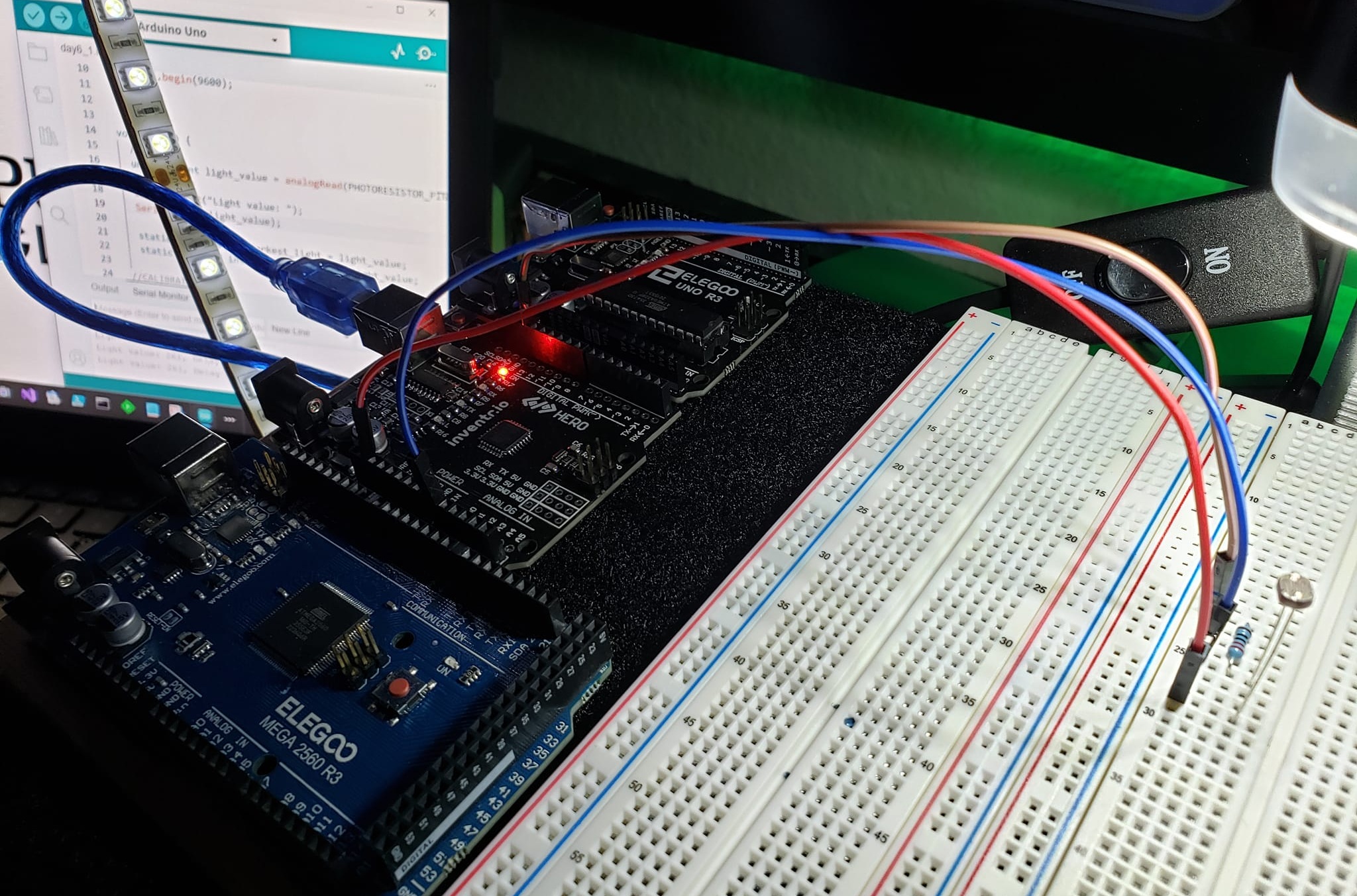
In this project, I create a photosensitive built-in LED blinker, which is controlled through programming the Arduino microcontroller.
The built-in LED blinks at a rate determined by the ambient light level, with darker environments leading to faster blinking and brighter environments leading to slower blinking. This behavior is achieved by dynamically adjusting the delay between LED on and off states based on the current light intensity. By dynamically, I mean the photoresistor is constantly changing its resistance due to varying light intensity. You can monitor that change and use the returned data in configuring the LED blink delay. Pretty cool, huh?
PARTS
1 x Arduino UNO R3
1 x 220 ohm resistor
1 x 5528 photoresistor
3 x Jumper wires
1 x Breadboard
5 volt power source
MEDIA
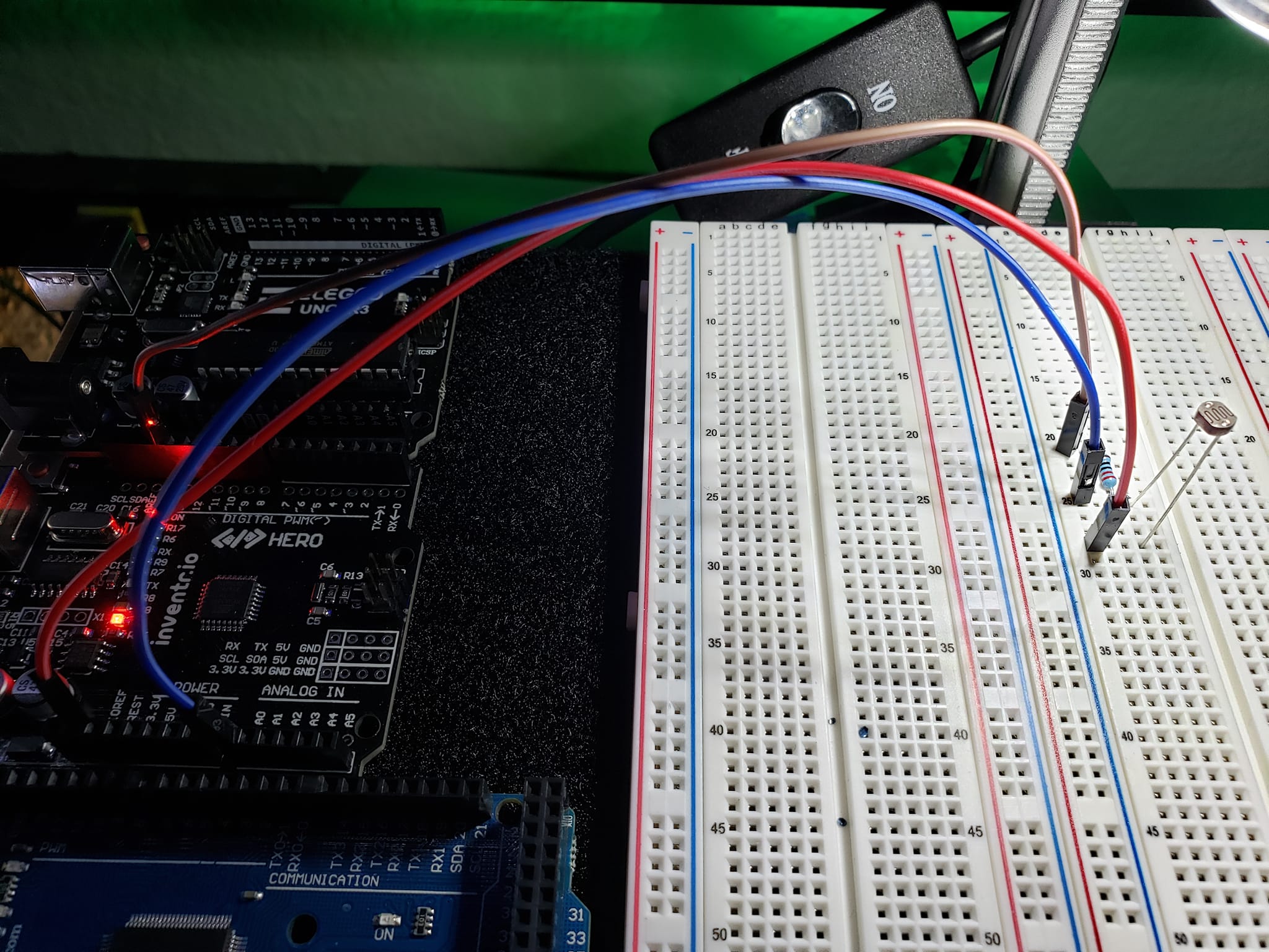
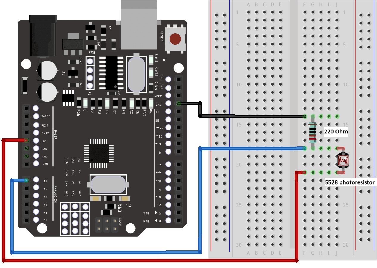
CONNECTIONS
220R to Ground on controller
220R to A0 on controller
5528 Photoresistor to 5V on controller
5528 Photoresistor to 220R
OPERATIONS
- Initialization:
- Pins are configured: LED_BUILTIN as an output for controlling the LED and PHOTORESISTOR_PIN as an input to read the analog value from the photoresistor.
- Serial communication is started for debugging purposes. Make sure you click the little monitor icon in the top right of the Arduino app (looks almost like a little magnify glass).
- Loop Function:
- Reads the analog value from the photoresistor, representing the ambient light level.
- Calibrates the darkest and brightest light values observed so far to normalize light readings.
- Maps the current light value to a delay value between MIN_DELAY and MAX_DELAY, which will control the blink rate of the LED. The darker the environment, the shorter the delay, leading to faster blinking, and vice versa.
- Turns on the LED for a duration determined by the calculated delay value.
- Turns off the LED for the same duration.
- The loop continues, constantly adjusting the LED blink rate based on the current light level.
CODE
#include "Arduino.h"

// MrNetTek
// eddiejackson.net
// 4/9/2024
// free for public use
// free to claim as your own

// DEFINE CONSTANTS
const byte PHOTORESISTOR_PIN = A0;     // PIN CONNECTED TO THE PHOTOSENSOR
const unsigned int MIN_DELAY = 50;     // MINIMUM DELAY FOR LED BLINK (IN MILLISECONDS)
const unsigned int MAX_DELAY = 500;    // MAXIMUM DELAY FOR LED BLINK (IN MILLISECONDS)

void setup() {
  pinMode(LED_BUILTIN, OUTPUT);        // SET LED PIN AS OUTPUT
  pinMode(PHOTORESISTOR_PIN, INPUT);   // SET PHOTOSENSOR PIN AS INPUT

  // START SERIAL COMMUNICATION FOR DEBUGGING
  Serial.begin(9600);
}

void loop() {
  // READ THE LIGHT VALUE FROM THE PHOTOSENSOR (0-1024)
  unsigned int light_value = analogRead(PHOTORESISTOR_PIN);

  // PRINT LIGHT VALUE TO SERIAL MONITOR FOR DEBUGGING
  Serial.print("Light value: ");
  Serial.print(light_value);

  // STATIC VARIABLES FOR CALIBRATION
  static unsigned int darkest_light = light_value;
  static unsigned int brightest_light = light_value;

  // CALIBRATION: UPDATE DARKEST AND BRIGHTEST LIGHT VALUES
  if (light_value < darkest_light) {
    darkest_light = light_value;
  }
  if (light_value > brightest_light) {
    brightest_light = light_value;
  }

  // MAP LIGHT VALUE TO DELAY VALUE BETWEEN MIN_DELAY AND MAX_DELAY
  unsigned int delay_value = map(light_value, darkest_light, brightest_light, MAX_DELAY, MIN_DELAY);

  // PRINT DELAY VALUE TO SERIAL MONITOR FOR DEBUGGING
  Serial.print(", Delay value: ");
  Serial.println(delay_value);

  // TURN ON LED
  digitalWrite(LED_BUILTIN, HIGH);
  delay(delay_value);

  // TURN OFF LED
  digitalWrite(LED_BUILTIN, LOW);
  delay(delay_value);
}
NOTES
Tags: Arduino, maker, builder, engineer, inventor, Project Aquarius