Aquarius: 1 2 3 4 5 6 7 8 9 10 11 12 13
![]()
![]()
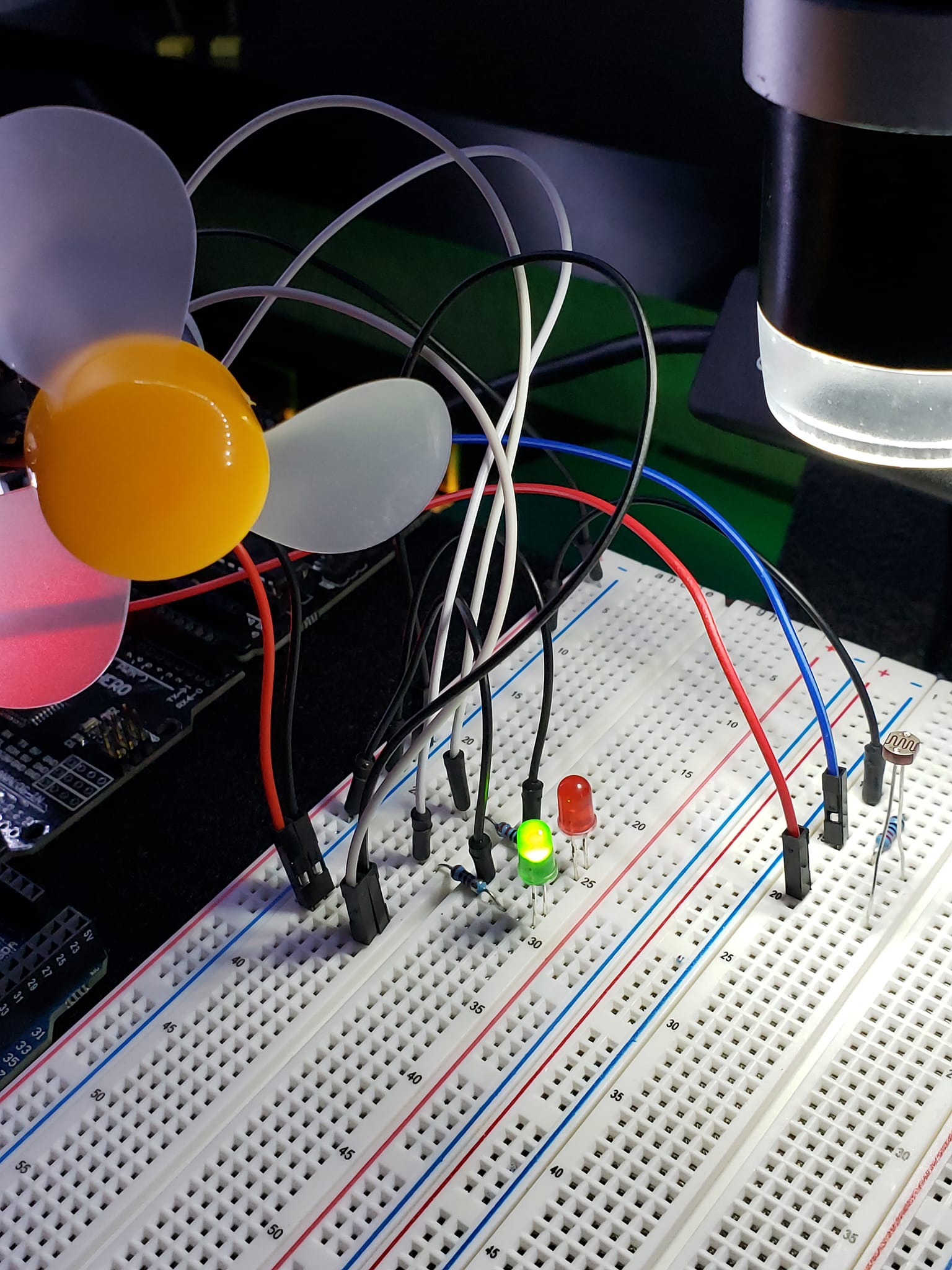
In this project, I build upon the ideas in Project 2, which has two LEDs and a photoresistor. I added a fan to project 3. The fan simulates a cooling system during charging. The red LED will be lit while the fan cools the system. When the simulation is complete—when the counter reaches 100%—the LED will be green, and the fan will shut off.
PARTS
1 x Arduino UNO R3
3 x 220 Ohm Resistors
1 x Red LED
1 x Green LED
1 x 5528 Photoresistor
5 x Jumper Wires
1 x Breadboard
1 x 3V-6V Fan
5 Volt Power Source
MEDIA

VIDEOS
![]()
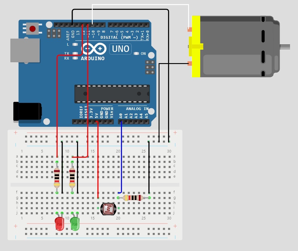
CONNECTIONS
Ground rail to Ground on controller
220R to A0 on controller
5528 Photoresistor to 5V on controller
220R to ground rail
5528 Photoresistor to 220R
Red LED+ to 220R, 220R to pin12
Red LED- to ground rail
Black LED+ to 220R, 220R to pin11
Black LED- to ground rail
Fan+ to pin10
Fan- to ground rail
OPERATIONS
Initialization (Setup Function):
-
- Pin Configuration: The setup function initializes the pins used in the circuit:
- PHOTORESISTOR_PIN is set as an input for reading values from the photoresistor.
- RED_LED_PIN and GREEN_LED_PIN are set as outputs for controlling the red and green LEDs, respectively.
- FAN_PIN is set as an output for controlling the fan.
- Serial Communication: Serial communication is initiated at a baud rate of 9600 for debugging purposes.
- Initial Delay: A short delay of 1000 milliseconds is added for stability.
- Pin Configuration: The setup function initializes the pins used in the circuit:
- Main Loop (Loop Function):
-
- Battery Charging Simulation:
- If the battery level is below its maximum capacity (BATTERY_CAPACITY), it increments based on the analog reading from the photoresistor.
- The battery level is checked to ensure it does not exceed the maximum capacity.
- Display Battery Charge Level:
- The function printBatteryChargeLevel is called to print the current battery charge level to the serial monitor.
- If the battery is not fully charged, it prints the percentage of charge.
- Once fully charged, it prints “FULLY CHARGED”.
- Control LEDs and Fan:
- The function controlLEDs is called to manage the states of the LEDs and the fan based on the battery level.
- If the battery is charging, the red LED and the fan are turned on, and the green LED is turned off.
- Once the battery is fully charged, the green LED is turned on, and the red LED and fan are turned off.
- Battery Charging Simulation:
-
- Sub-functions:
-
- printBatteryChargeLevel:
- Prints the battery level as a percentage to the serial monitor if the battery is not fully charged.
- Prints “FULLY CHARGED” once the battery reaches its full capacity.
- Prints the battery level as a percentage to the serial monitor if the battery is not fully charged.
- controlLEDs:
- Manages the states of the red and green LEDs and the fan.
- Turns on the red LED and the fan while the battery is charging.
- Turns on the green LED and turns off the red LED and fan once the battery is fully charged.
- printBatteryChargeLevel:
-
CODE
#include "Arduino.h"

// MrNetTek
// eddiejackson.net
// 7/6/2024
// free for public use
// free to claim as your own

#include "Arduino.h"

// DEFINE PIN CONSTANTS
const byte PHOTORESISTOR_PIN = A0; // Analog pin for photoresistor
const byte RED_LED_PIN = 12; // Red LED for charging indication
const byte GREEN_LED_PIN = 11; // Green LED for fully charged indication
const byte FAN_PIN = 10; // Pin for cooling fan control

// MAXIMUM BATTERY CAPACITY CONSTANT
const unsigned int BATTERY_CAPACITY = 50000;

void setup() {
  // Initialize pin modes
  pinMode(PHOTORESISTOR_PIN, INPUT); // Set photoresistor pin as input
  pinMode(RED_LED_PIN, OUTPUT); // Set red LED pin as output
  pinMode(GREEN_LED_PIN, OUTPUT); // Set green LED pin as output
  pinMode(FAN_PIN, OUTPUT); // Set fan pin as output

  // INITIALIZE SERIAL COMMUNICATION FOR DEBUGGING
  Serial.begin(9600);

  // INITIAL DELAY FOR STABILITY
  delay(1000);
}

// VARIABLE TO STORE THE CURRENT BATTERY LEVEL
unsigned int battery_level = 0;

void loop() {
  // CHECK IF BATTERY IS NOT FULLY CHARGED
  if (battery_level < BATTERY_CAPACITY) {
    // INCREMENT BATTERY LEVEL BASED ON PHOTORESISTOR READING
    battery_level += analogRead(PHOTORESISTOR_PIN);

    // ENSURE BATTERY LEVEL DOES NOT EXCEED MAXIMUM CAPACITY
    if (battery_level > BATTERY_CAPACITY) {
      battery_level = BATTERY_CAPACITY;
    }
  }

  // PRINT CURRENT BATTERY CHARGE LEVEL TO SERIAL MONITOR
  printBatteryChargeLevel();

  // CONTROL LEDS AND FAN BASED ON BATTERY LEVEL
  controlLEDs();

  // DELAY FOR TIMING PURPOSES
  delay(100);
}

void printBatteryChargeLevel() {
  // CHECK IF BATTERY IS NOT FULLY CHARGED
  if (battery_level < BATTERY_CAPACITY) {
    // PRINT BATTERY PERCENTAGE TO SERIAL MONITOR
    Serial.print("Battery Level: ");
    Serial.print(((double)battery_level / (double)BATTERY_CAPACITY) * 100);
    Serial.println("%");
  } else {
    // PRINT FULLY CHARGED MESSAGE TO SERIAL MONITOR
    Serial.println("FULLY CHARGED");
  }
}

void controlLEDs() {
  // CHECK IF BATTERY IS NOT FULLY CHARGED
  if (battery_level < BATTERY_CAPACITY) {
    // INDICATE CHARGING IN PROGRESS: TURN ON RED LED, TURN OFF GREEN LED, TURN ON FAN
    digitalWrite(RED_LED_PIN, HIGH);
    digitalWrite(GREEN_LED_PIN, LOW);
    digitalWrite(FAN_PIN, HIGH);
  } else {
    // INDICATE FULLY CHARGED: TURN OFF RED LED, TURN ON GREEN LED, TURN OFF FAN
    digitalWrite(RED_LED_PIN, LOW);
    digitalWrite(GREEN_LED_PIN, HIGH);
    digitalWrite(FAN_PIN, LOW);
  }
}
NOTES
Tags: Arduino, maker, builder, engineer, inventor, Project Aquarius