Aquarius: 1 2 3 4 5 6 7 8 9 10 11 12 13
![]()
![]()
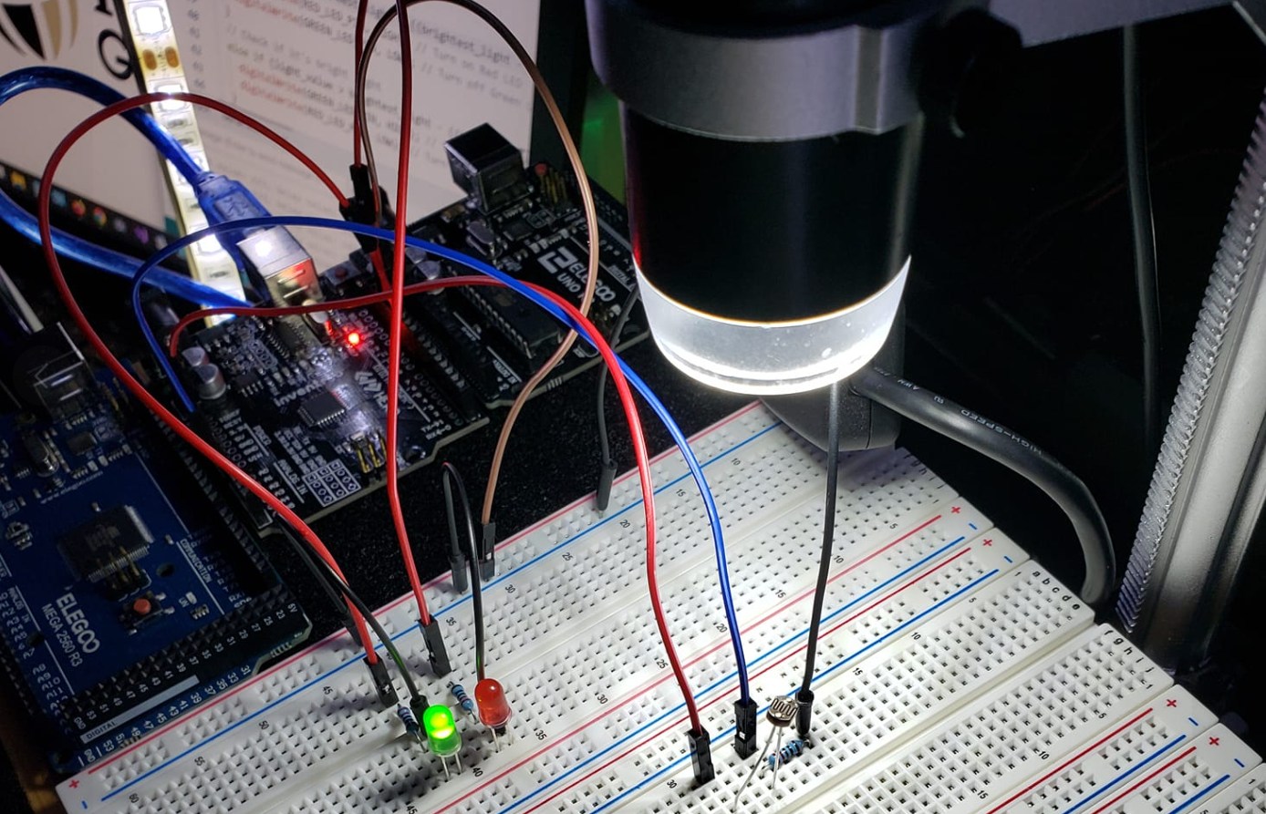
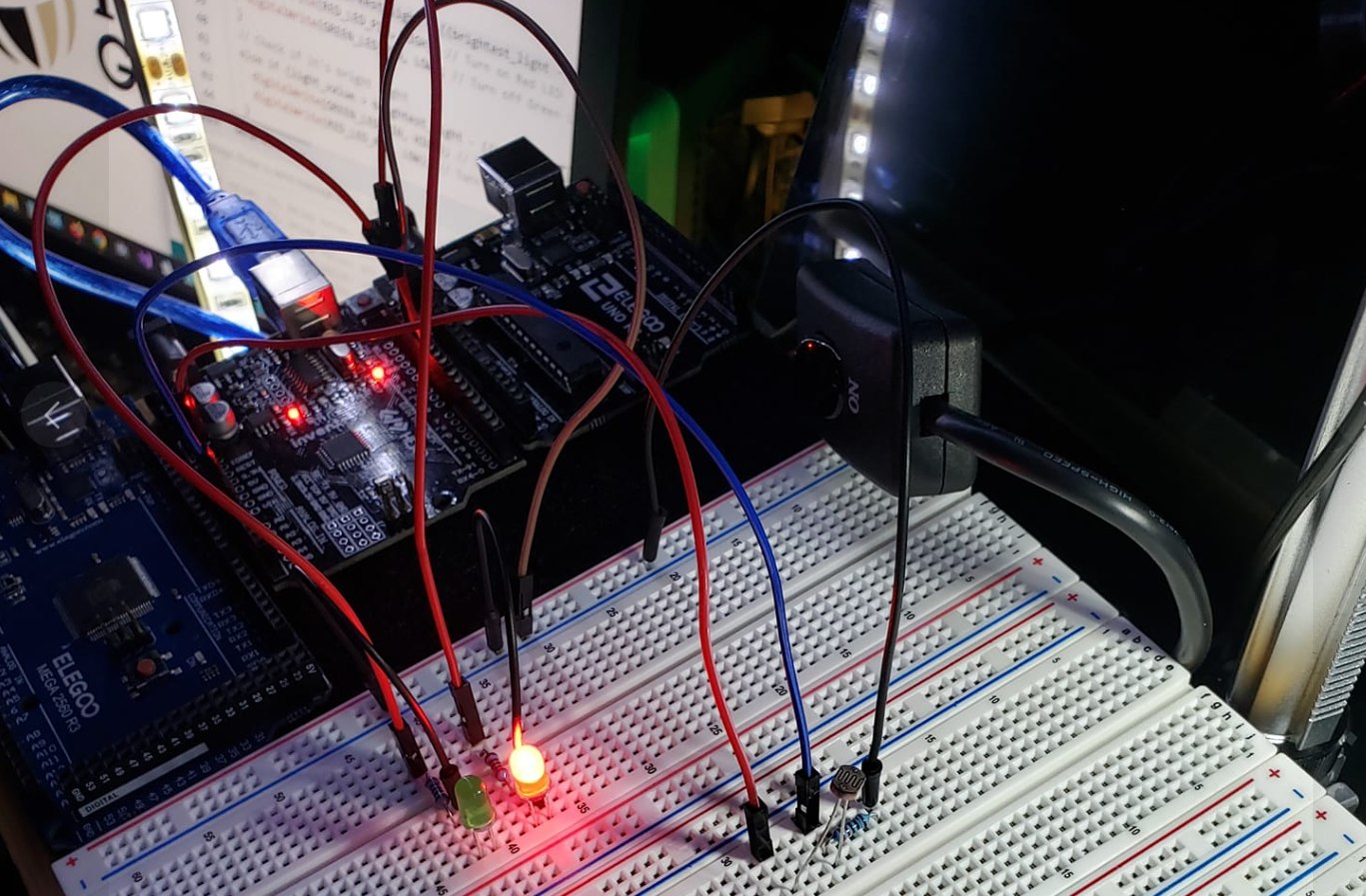
In this project, I build upon the ideas in Project 1, and use discrete LEDs on a breadboard to visibly show when low or bright light is detected. Red is low light. Green is bright light.
It is essentially a light-sensing system using a photoresistor and two LEDs to indicate the ambient light level. The logic is controlled through programming the Arduino microcontroller.
PARTS
1 x Arduino UNO R3
3 x 220 ohm resistors
1 x Red LED
1 x Green LED
1 x 5528 photoresistor
5 x Jumper wires
1 x Breadboard
5 volt power source
MEDIA
VIDEOS
![]()
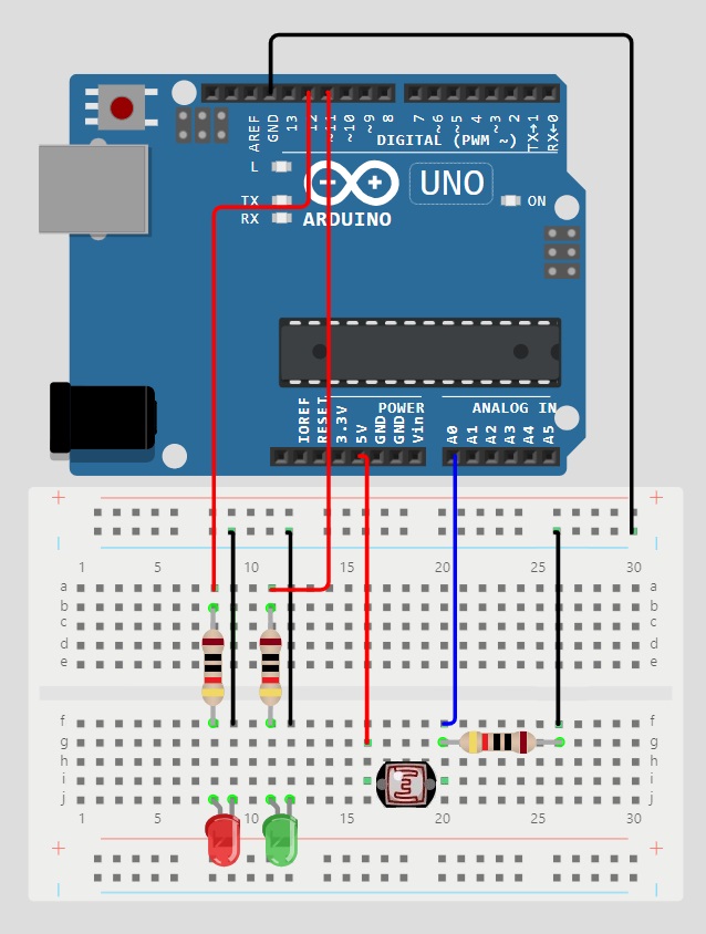
CONNECTIONS
Ground rail to Ground on controller
220R to A0 on controller
5528 Photoresistor to 5V on controller
220R to ground rail
5528 Photoresistor to 220R
Red LED+ to 220R, 220R to pin12
Red LED- to ground rail
Black LED+ to 220R, 220R to pin11
Black LED- to ground rail
OPERATIONS
- Initialization (Setup Function):
- The setup function initializes the pins used in the circuit:
- LED_BUILTIN pin as an output for the built-in LED.
- PHOTORESISTOR_PIN as an input for the photoresistor.
- RED_LED_PIN and GREEN_LED_PIN as outputs for the red and green LEDs, respectively.
- It also starts serial communication at a baud rate of 9600 for debugging purposes. Make sure you click the little monitor icon in the top right of the Arduino app (looks almost like a little magnify glass).
- The setup function initializes the pins used in the circuit:
- Main Loop (Loop Function):
- Light Intensity Measurement:
- Reads the analog value from the photoresistor connected to PHOTORESISTOR_PIN.
- Prints the light value to the serial monitor for debugging.
- Calibration:
- Initializes variables darkest_light and brightest_light with the current light value for calibration.
- Updates darkest_light and brightest_light if the current light value is darker or brighter than the previous values, respectively.
- Mapping Delay:
- Maps the current light value to a delay value using the map() function. This delay value determines how fast the built-in LED blinks, based on the light intensity.
- Prints the delay value to the serial monitor for debugging.
- Blinking Built-in LED:
- Turns on the built-in LED ( LED_BUILTIN ) for a duration determined by the delay value.
- Then, turns off the built-in LED for the same duration, creating a blinking effect.
- Control of Red and Green LEDs:
- Checks the light intensity to determine whether it is low, medium, or high:
- If the light value is below one-third of the range between darkest_light and brightest_light , the red LED is turned on, indicating low light.
- If the light value is above two-thirds of the range, the green LED is turned on, indicating high light.
- Otherwise, both LEDs are turned off, indicating medium light.
- Checks the light intensity to determine whether it is low, medium, or high:
- Loop Continues:
- The loop function repeats continuously, continually measuring light intensity, adjusting LED behavior, and blinking the built-in LED accordingly.
- Light Intensity Measurement:
CODE
#include "Arduino.h"

// MrNetTek
// eddiejackson.net
// 4/12/2024
// free for public use
// free to claim as your own

// DEFINE PIN ASSIGNMENTS
const byte PHOTORESISTOR_PIN = A0; // Pin connected to the photoresistor
const byte RED_LED_PIN = 12;        // Red LED pin
const byte GREEN_LED_PIN = 11;      // Green LED pin

// DEFINE DELAY CONSTANTS
const unsigned int MIN_DELAY = 50;  // Minimum delay between LED toggles
const unsigned int MAX_DELAY = 500; // Maximum delay between LED toggles

void setup() {
  // SET PIN MODES
  pinMode(LED_BUILTIN, OUTPUT);      // Built-in LED pin as output
  pinMode(PHOTORESISTOR_PIN, INPUT); // Photoresistor pin as input
  pinMode(RED_LED_PIN, OUTPUT);      // Red LED pin as output
  pinMode(GREEN_LED_PIN, OUTPUT);    // Green LED pin as output

  // START SERIAL COMMUNICATION
  Serial.begin(9600);
}

void loop() {
  // READ LIGHT INTENSITY FROM THE PHOTORESISTOR
  unsigned int light_value = analogRead(PHOTORESISTOR_PIN);

  // PRINT LIGHT VALUE TO SERIAL MONITOR
  Serial.print("Light value: ");
  Serial.print(light_value);

  // INITIALIZE VARIABLES FOR CALIBRATION
  static unsigned int darkest_light = light_value;
  static unsigned int brightest_light = light_value;

  // CALIBRATION
  // UPDATE DARKEST AND BRIGHTEST LIGHT VALUES
  if (light_value < darkest_light) {
    darkest_light = light_value;
  }
  if (light_value > brightest_light) {
    brightest_light = light_value;
  }

  // MAP LIGHT VALUE TO DELAY VALUE
  unsigned int delay_value = map(light_value, darkest_light, brightest_light, MAX_DELAY, MIN_DELAY);
  Serial.print(", Delay value: ");
  Serial.println(delay_value);

  // TOGGLE BUILT-IN LED WITH CALCULATED DELAY
  digitalWrite(LED_BUILTIN, HIGH);
  delay(delay_value);
  digitalWrite(LED_BUILTIN, LOW);
  delay(delay_value);

  // CHECK LIGHT INTENSITY AND CONTROL LEDS ACCORDINGLY
  // CHECK LOW LIGHT - CHANGE RANGE HERE
  if (light_value < darkest_light + ((brightest_light - darkest_light) / 3)) {
    digitalWrite(RED_LED_PIN, HIGH);    // Turn on Red LED
    digitalWrite(GREEN_LED_PIN, LOW);   // Turn off Green LED
  }
  // CHECK BRIGHT LIGHT - CHANGE RANGE HERE
  else if (light_value > brightest_light - ((brightest_light - darkest_light) / 3)) {
    digitalWrite(GREEN_LED_PIN, HIGH);  // Turn on Green LED
    digitalWrite(RED_LED_PIN, LOW);     // Turn off Red LED
  }
  // BETWEEN RANGE
  else {
    digitalWrite(RED_LED_PIN, LOW);     // Turn off Red LED
    digitalWrite(GREEN_LED_PIN, LOW);   // Turn off Green LED
  }
}
NOTES
Tags: Arduino, maker, builder, engineer, inventor, Project Aquarius